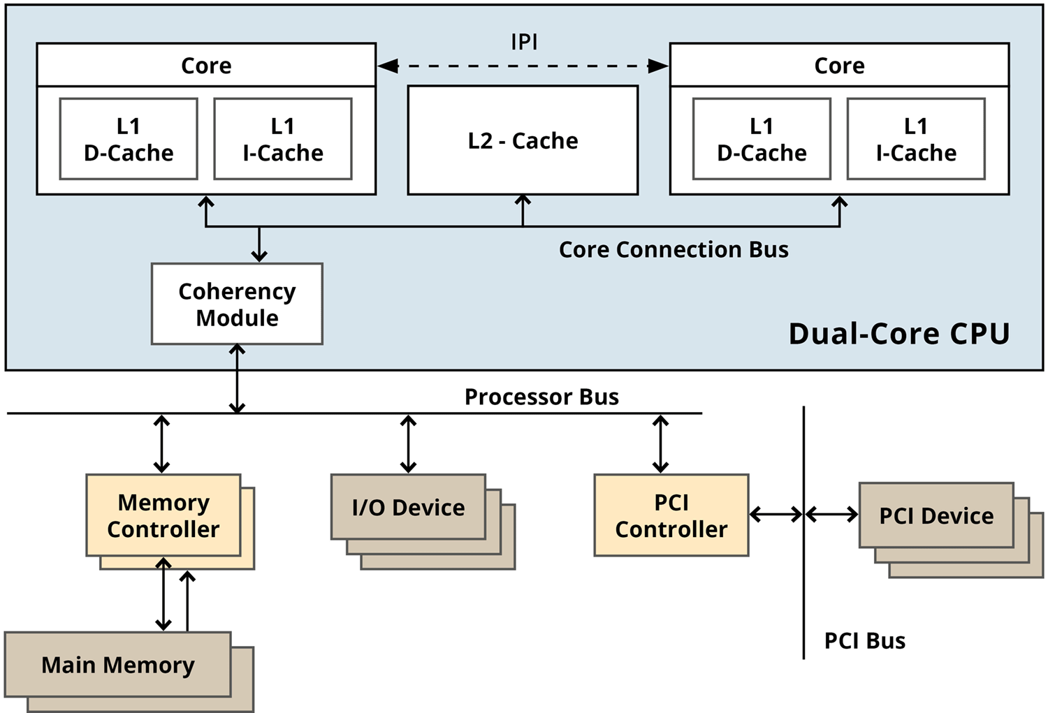
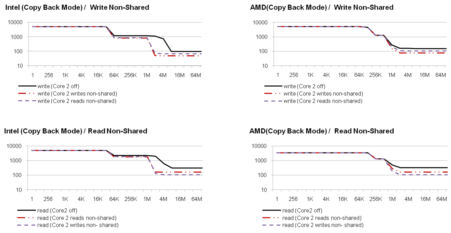
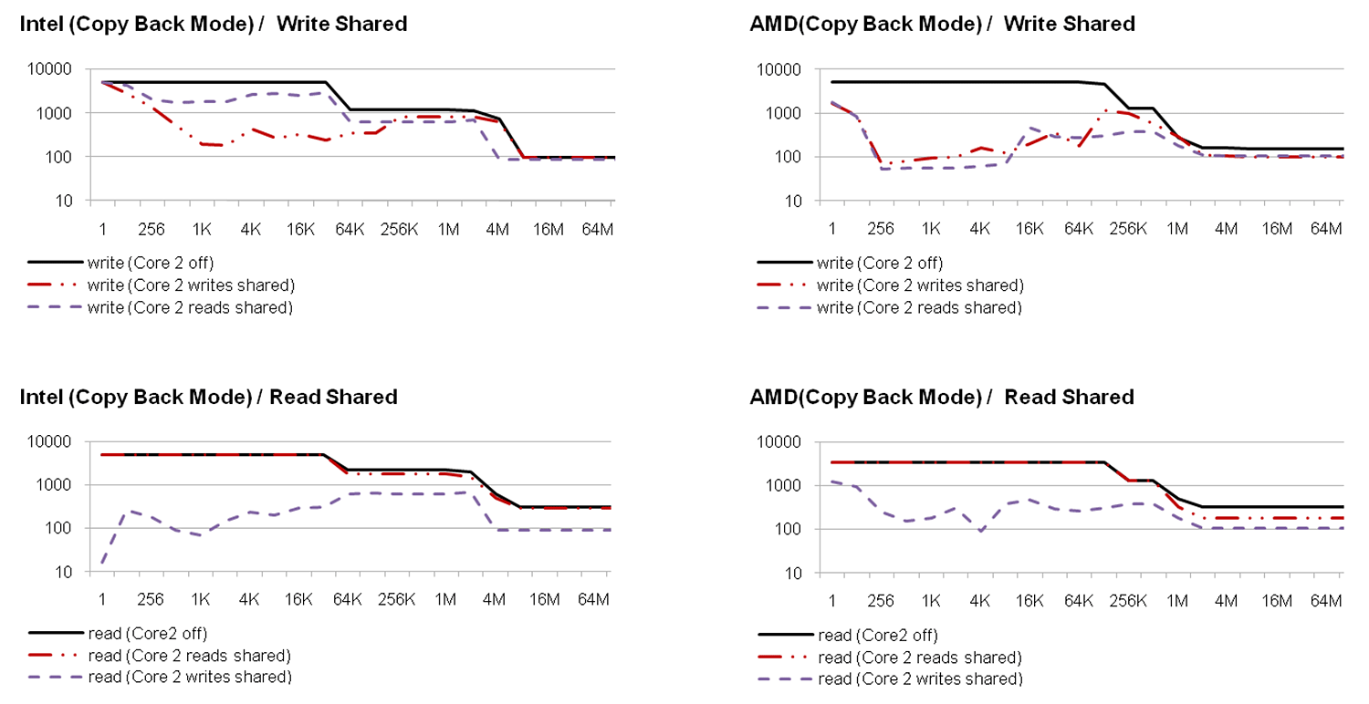
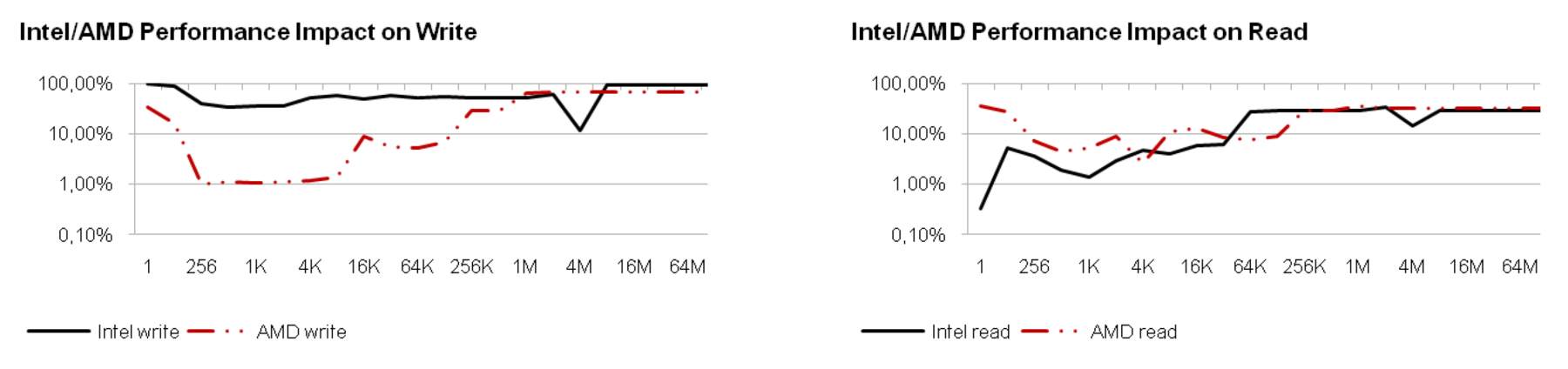
Professional Articles

Avionics

How to address Certification for Multi-Core based IMA Platforms

In modern aircrafts, more and more functions traditionally implemented as Line Replaceable Units (LRUs) will be hosted by Integrated Modular Avionics (IMA) modules. At the same time new aircraft programs will require new safety functions, information services and comfort features which will also increase the demand for processing performance of IMA modules.

The traditional approach to provide more processing bandwidth was to increase the CPU clock frequency, increase pseudo-parallel processing on instruction level through instruction pipelines and speculative program executions and to increase the cache size and number of cache levels. With today's technology, this approach has reached its limit. Increasing CPU frequency causes disproportionate power consumption and thermal dissipation loss and raises more and more problems due to chip internal and external crosstalk, signal delays and reflection. Existing parallelism and dependencies on code level prevent further performance improvement through parallel execution on instruction level. To further increase processor performance, the chip industry has switched to a multi-core design for the high performance processors. 

The development of multi-core based high performance IMA platforms will be a necessary step to reach a larger scale integration on function level. The question is, "Can a multi-core based platform reach the same level of determinism as a single core platform and can this be demonstrated?"

This paper addresses certification aspects of multi-core based IMA platforms with the focus on today's technologies and processes. The paper provides an analysis of potential hardware and software related interference channels between partitions running on a multi-core based platform. Different core software concepts found in existing implementations like asymmetric multi processing (AMP) and symmetric multi processing (SMP) concepts are evaluated with respect to partitioning aspects.  


Introduction

In all industrial areas, more and more safety related services are implemented using electronic devices and the demand for information, comfort and entertainment services is constantly growing. At the same time, product and environmental constraints require a reduction of size, weight and power consumption which leads to a high function integration level. Integration of software modules with different safety, robustness and quality requirements developed by independent teams requires well defined component interfaces, development processes and an embedded platform which supports a high level of function segregation and fault containment. The challenges of function integration has led to the development of standards and frameworks like AUTOSAR for the automotive industry and IMA for the avionics and space industry.

For the IMA architecture, the main objectives is the safe integration of application developed for different safety levels, which requires a strict partitioning of platform resources. 

At the beginning of AUTOSAR, the main focus was the reduction of development and maintenance costs through standardized and interchangeable software components to enable competition between software suppliers. Today, more and more safety related functions like drives assistance, crash avoidance or crashworthiness systems are developed while the tendency is also to reduce the number of ECUs which also leads to need for a partitioning concept which is addressed in AUTOSAR release 4.


Certification Considerations

Integration of software services with diverging functional, robustness, safety and security needs requires an embedded platform which 

  • provides sufficient CPU performance, memory resources and I/O bandwidth,
  • is sufficiently reliable, 
  • has a deterministic and predictable real-time behavior,
  • supports a safe and secure resource and CPU time partitioning, and
  • is certifiable according to the applicable safety and security standards.

What are the main difference regarding certification between single core and a multi-core based platform?


Processor Design Assurance

Today's IMA platforms typically use processors like the IBM 603, 604, 75x, or 74xx families. These processors are based on the RISC architecture and, except to the PPC 74xx, they have a fairly simple cache and pipeline architecture. To a certain extend design documents are available to support the certification process. Due to the frequent use in avionic platforms there is a lot of In Service Experience available which reduces the risk of undetected systematic errors. Certification authorities have accepted IMA platforms based on this processor for applications with a criticality up to level A.

A multi-core processors is typically the successor of an highly advance single-core processor implementing all the features like complex instruction pipelines, branch prediction means and multi-level caches. In addition they need cache coherency modules and crossbars to interconnect the cores. Multi-core processors mark the cutting-edge in chip technology and it is therefore very unlikely that the chip manufactures' will provide detailed chip design information to support the platform certification process. Another important point is that multi-core CPUs are often only available as System on Chip (SoC) devices, especially CPUs from the PowerPC family. Microprocessors design assurance is normally based on their use as COTS and the application of DO-178B with target testing for the software they support.

For microcontrollers, the situation is different. Due to the integration of processing component and peripheral components like bus controllers and communication devices, parts of the hardware certification process may be bypassed. Certification agencies require additional evidence that the processes used in the design of digital devices provide a level of design assurance commensurate with the intended use of that device. The problem is now that it is not feasible to apply a DO-254 compliant certification process without detailed design documentation of the device. As an alternative approach, certification authorities accept in service experience in comparable applications if it can be demonstrated that no problems have been encountered. A comparable application means an avionic application. This causes a kind of bootstrap problem. To overcome this problem it is necessary to start using promising chip candidates in low critical application and gather systematically all in-service data and problem reports. 


Error Detection and Correction

The processors used in avionic platforms typically implement Error Correction Codes (ECC) to detect and correct single or multi-bit error in registers and caches. The PPC 750GX supports the lock-step mode which allows to connect two or more of these processors with a voter (e.g. a 2oo3 voter) to build a platform which is extremely Single Event Upset (SEU) resistant.

Multi-core processors are more sensitive to SEU than the processors used in existing IMA platforms due to the larger chip surface and decreasing structure size [1], [2]. The selection of a multi-core processor for an avionic platform need consider a sufficient ECC protection. Additional redundancy may need to be implemented on system level to compensate for the higher probability of SEUs.


Resource and Time Partitioning

Single and multi-core processors use the same techniques to support resource protection, both use the concept of privilege levels and provide a Memory Management Unit (MMU) to controls access to privileged instructions and processor registers, physical memory and memory mapped I/O devices. With regards to the certification of resource partitioning aspects, there is no fundamental difference between a single and a multi-core based platform.

Time partitioning is more complicated on a multi-core based system. On a single core processor, there is only one thread of execution at a time. This thread might be interrupted by an asynchronous event in which case control is passed to the corresponding handler but there is no concurrent execution. An exception may be an I/O device which has Direct Memory Access (DMA). capabilities {2}.  

On a multi-core processor, parallel execution is the normal case which may lead to interference between applications running on different cores. These interference channels are discussed in the following sections.


Hardware Interference Channels

Applications running on different cores of a multi-core processor are not executing independently from each other. Even if there is no explicit data or control flow between these applications, a coupling exists on platform level since they are implicitly sharing platform resources. A platform property which may cause interference between independent applications is called a hardware interference channel. The analysis of hardware interference channels requires a deep understanding of the platform architecture including the CPU internals.


Platform Overview

The scope of this paper is the upgrade of existing concepts to COTS multi-core processors rather than an evaluation of new processor or platform architectures. Therefore we assume a platform architecture found in today's IMA CPIOM modules and replace the single core CPU by a multi-core CPU. The multi-core processors addressed in this paper implement the Unified Memory Model, which means that all cores share the same physical address space. This simplifies the platform design since it requires only one external processor bus and it allows inter core communication through shared physical memory. Figure 1 shows the typical architecture of such a platform.


Figure 1: Dual Core-based CPIOM (Core Processing & I/O Modules) Platform

Some of the hardware components like the memory controller, the PCI controller or other I/O device might be integrated together with the CPU to form a Multi-Processor System-On-Chip (MPSoC) device. 


CPU Cores

It is assumed, that the CPU cores by itself execute independently as long as they are not accessing shared resources or use Inter Processor Interrupts (IPIs). IPIs are addressed together with the software related interference channels since they need to be actively triggered by software.


Caches

Two different aspects of the cache architecture may introduce cross CPU interference channels: Cache Coherency and Cache Sharing.

Before we investigate the interference channels introduced by the processor caches, we provide a short overview of the basic cache architecture.

The memory system can be considered as hierarchical system with the CPU core at the bottom, followed by one or more levels of caches and the memory at the top. The cache which is directly connected to the CPU is the L1 cache followed by the L2 and so on. This highest cache level is connected to the external bus and thus to the main memory.

A date request which cannot be satisfied on a given level is delegated to the next higher level. With the increasing cache level, the cache size increases but also the access latency.

Data are transferred between the different levels of the memory system in fixed size chunks called cache lines. The size of a cache line is specific to the processor architecture, typical values are 32 or 64 bytes. Cache lines are organized in cache sets and one or more cache sets form the entire level N cache. Most modern caches are Virtually Indexed - Physically Tagged (VIPT) which means that the cache line within a cache set is determined based on the virtual address and the physical address is used as cache tag. With a given cache size S, the number of cache sets N, the cache line size L, the cache index I for a given virtual address V is calculated as:

I = (V mod (S / N)) / L

This means that all addresses of the form V + n*(S/N), where n is a positive or negative integer, lead to the same cache index. 

If a new entry has to be stored in the cache, all sets will be searched for an invalid entry at the corresponding index. If an invalid entry is found, it will be used to store the new value, otherwise an existing entry will be replaced which may require that the corresponding data are written back to memory before the entry can be used for the new data. The algorithm used to replace a cache line is CPU specific. Often LRU (Line Replaceable Units) or random algorithms are used.


Cache Sharing

The L1 cache is typically divided into a data and an instruction cache while all other levels store data and instructions. Most multi-core processors have a dedicated L1 data and instruction cache per core while the architecture of the L2 and L3 cache varies with the CPU family {3}.

Shared caches are an essential cause of interference in a multi-core processor. A comparison of read and write throughput between an Intel Pentium Dual Core E5300 and an AMD Athlon II x2 processor shows the impact of a shared L2 cache. 

The Intel processor has a per-core 32 Kbyte + 32 Kbyte L1 data and instruction cache and a shared 2 Mbyte unified L2 cache.

The AMD processor has a per-core 64 Kbyte + 64 Kbyte L1 data and instruction cache and a per-core512 Kbyte unified L2 cache.

To measure the interference between two cores caused by cache sharing, both cores are reading or writing on a data set of a fixed size. The size of the data set is increased from a value which is small enough to fit in both processor's L1 caches to a size which is larger than both processor's L2 cache. The data sets do not overlap to avoid interference caused by cache coherency effects. The data are accessed in 32 bit entities with an increment of 33 words to ensure that subsequent data are not read from the same cache line and also not from the next cache line which may have been pre-fetched by the processor. First the data throughput is measured for read and write accesses when the other core is inactive, and then when both cores are reading and writing simultaneously.

Figure 2 shows the results for the two CPUs (note the logarithmic scale of the y-axis). The results can be interpreted as follows:

If the data set is small enough to fit in the L1 cache (private for each core) the Intel and AMD processor show no loss of performance if the second core becomes active.

If the data set is smaller than the L2 cache accessible by the cores and the L2 cache is not shared (AMD processor), the second core again causes no performance degradation.

If the data set is smaller than the L2 cache visible to a core and the L2 cache is shared (Intel processor), the worst case performance loss through the second core depends on the data set size and is between 30% and 95% for write operations and 19% and 92% for read accesses. The largest impact (92%) is observed if the data set has exactly the size of the L2 cache because with one core the data still completely fit into the L2 cache while with 2 cores all data need to be fetched from memory which means that we are comparing the performance of the L2 cache with the performance of the memory bus.

If the data set is significantly larger than the L2 cache, the worst case performance loss caused by the second core is ~50%for read and write operations.


Figure 2: Read and Write Throughput on separated Data Sets (Mbyte)

Cache Coherency

Another important aspect related to the use of caches is the consistency of local caches connected to a shared resource. Cache coherency is of particular importance in multi-core systems with unified memory. Cache coherency means:

If one of the local caches of core CA contains a reference to a physical resource Px and the cached value is more recent than the value stored in Px, any read access from any core (including core CA) must provide the value cached by core CA.

Coherency between caches is maintained by means of the cache coherency protocol. A detailed description of the different cache coherency protocols can be found in [3]. The principle of the cache coherency protocol can be explained on the MSI protocol.

The MSI protocol defines the states Modified, Shared and Invalid for each cache line.

A modified cache line has data which are written to the cache but not yet to the reference resource. Only one cache can have a modified cache line for a given resource, in all other caches the corresponding entry must be invalid.

A shared cache line stores the same data as the reference resource. Multiple caches may have a shared cache line referencing the same physical resource.

An invalid cache line does not reference any physical resource.

The actions performed by the MSI protocol to keep the caches in a consistent state are shown in Table 1 for write and read cycles. The local cache is the cache of the active core performing the read or write operation, the remote caches are the caches of the other cores which are considered to be passive with respect to the pending access. The state transitions have to be considered for any pair of local and remote caches. The shaded cells show state transitions which have impact on the passive cores.


Table 1: MSI State Transitions for Write and Read Cycles

A special case of performance degradation due to the cache coherency is the so-called false sharing [4]. False sharing can arise if two cores operate on logically independend data but these data are physically stored in a memory region whichs ends up in the same cache line. In this case the performance reduction is the same as if the processors would access the same data.

To measure the interference caused by the coherency protocol, we use the same setup as for the previous measurement, but now the two cores operate on the same data set to generate cache reference to the same physical memory in both cores.

If the data set is small enough, each write acces of one core will invalidate the cache entry which is referenced next by the other core. Figure 3 shows the results for the two CPUs (note the logarithmic scale of the y-axis). The result shows that:

If both cores are only reading, the second core causes almost no performance impact over the entire range of data sets in case of the Intel processor while on the AMD processor the performance drops down to 50% if the data set is larger than the L2 cache.


Figure 3: Read and Write throughput on shared Data Sets (Mbyte)

If both cores are only writing, the Intel processor suffers much less from the concurrent read than the AMD processor but the dependency on the data set size is similar.

If one core is reading while the other core is writing the same data set, Intel and AMD processors behave completely different. Figure 4 shows the relative throughput for both processors compared to the throughput if only one core is active. On the Intel processor, the writing CPU suffers much less from a concurrent read than on the AMD processor, however the maximum performance loss is also 90% for the case that the data set size is 4 Mbyte. On the AMD processor the performance loss is 99% on small data sets and it moves towards 50% for large data sets. If we compare the read performance loss we see that on the Intel processor, that the reader is almost completely blocked on very small data sets. This effect does not appear on the AMD processor. If the data sets get larger, Intel and AMD behave similar. For midsize sets the loss is still around 90% on both processors.


Figure 4: Relative Performance Loss on concurrent Read and Write Operations

Data Buses

The results of the performance measurements (Figure 2 and 3) show that the bandwidth of the memory bus is shared between the cores. If the cores operate on a data set which is so large that the caches have no effect, the performance drops down to 50% if both cores are active. The same effect has been measured on the PCI bus. While a cache hit rate of 0% may be very unlikely when accessing memory, it is the normal case on the PCI bus since PCI devices are typically accessed with caches disabled.


Shared I/O Devices

The reduction of performance caused by concurrent access to a shared I/O device mainly depends on the bus which connects the device to the processor (e.g. the PCI bus) and on the device itself. A device which can only handle one request at a time may block a second request for hundreds of microseconds.


Shared Interrupts

On a multi-core platform, a hardware interrupt is typically routed to one core. If multiple devices are attached to one interrupt line and the devices are not served by the same core, the core who receives the interrupt must pass this interrupt also to the other core(s) forcing them to check the interrupt status of their devices. Shared interrupts may cause a significant interference between the cores and must be avoided by an appropriate platform design.


Software Interference Channels

One of the key components of an IMA module is the core software including the operating system. The core software must provide an execution environment for the hosted applications which on the one hand hides the platform characteristics from the hosted applications and on the other hand strictly controls the use of platform resources for all applications. While most hardware platforms and operating systems are designed for optimized average computing performance, IMA modules must distribute a high and constant level of computing bandwidth to applications according to the predefined time schedule. The system software must prevent unintended coupling between partitions due to access to shared resources and must not introduce additional interference channels due to concurrent access to the system software itself. Compared to a single core design, where asynchronous platform utilization with impact on the running application is mainly limited to interrupt processing and DMA transfers initiated by I/O devices, asynchronous access to platform and system software resources is the normal case on multi-core platforms.

The diversity of CPU and platform architectures and functional requirements leads to different concepts of multi-core support in the core software component. For a dual-core CPU an adapted ARINC 653 time partitioning concept might be appropriate while for a CPU with 32 or more cores, time partitioning might no longer make sense. In the following we assume a system software design which is compatible with the ARINC 653 partitioning concept but we assume, that specific partitions may need to utilize multiple cores.


Software Concepts for Multi-Core Platforms

Interference between software components running concurrently on different cores mainly depends on the software architecture and the way the software utilizes the cores. The following sections discuss the different concepts of using multi-core processors and the related interference issues.


Operating System Level

On operating system level, two concepts for utilizing multiple processor cores are distinguished:

The Asymmetric Multiprocessing (AMP or ASMP) and the Symmetric Multiprocessing (SMP).

The AMP approach utilizes a multi-core processor platform very much like a multi-processor system. Each core runs its own single-core aware system software layer. The cores are loosely coupled through distinct communication channels which may be based on inter processor interrupts, specific shared memory regions or other external devices.

The major advantages of the AMP approach are: 

  • The system software layer does not need to be multi-core aware which simplifies the design.
  • There is no implicit coupling through shared data and critical sections inside the system software layer.
  • Each core may run a system software layer which is optimized for the task to be performed. An example for this is a dual-core platform where one core is responsible for I/O processing and data concentration while the other core runs an ARINC 653 compliant OS which hosts the applications.

The disadvantages of the AMP approach are: 

  • All system software instances must be certified to the highest level applicable for the platform since they have full access to privileged processor registers and instructions.
  • Partitioning of platform resources is more complicated, especially if different system software layers are used. This limits the use of the APM concept to CPUs with a small number of cores.
  • Synchronization between applications running on different cores is more complex.
  • The AMP approach does not support parallel execution on application level.

Interference on an AMP platform is mainly caused by shared caches, memory and I/O buses and concurrent access to shared devices. Interference on the memory bus is hard to avoid while access to I/O devices may be limited to one core. Coherency problems are limited to distinct communication buffers and interference caused by the system software is limited to shared device handles.

The SMP approach uses one system software instance to control all cores and platform resources. The OS typically provides inter and intra partition communication services which transparently manage cross core communication. Device drivers are responsible to manage concurrent access to platform resources.

The advantages of the SMP approach are: 

  • There is only one system software instance responsible for the partitioning concept which limits the certification effort to one software package.
  • There is only one platform configuration layer required.
  • The SMP system software can completely isolate execution of critical tasks, e.g. by temporary disabling concurrent execution of non-trusted partitions.
  • SMP provides much more flexibility and allows a better load balancing than an AMP configuration.
  • Parallel execution on application level can be supported where interference between cores is of no concern, e.g. for non-safety related partitions.

The main disadvantages of the SMP approach are:

  • The system software layer is more complex since it needs to protect its internal data from concurrent access without significant impact on parallel service requests.
  • The internal data need to be arranged very carefully in order to avoid false sharing effects.
  • Due to the shared system software layer, an implicit coupling of unrelated execution threads cannot be completely avoided.

Compared to an AMP configuration the SMP approach adds an important source of potential interference which is the shared system software layer. A careful design however can limit the impact by the implementation of fine-grain critical sections. The internal data of the system software layer must be carefully arranged to avoid unintended coupling due to false sharing.


Parallel Execution on Thread Level

Parallel execution on thread level means that the programmer divides an application into multiple threads of execution and binds these threads to a processor core. The threads typically operate on the same data, e.g.. the applications data, bss and heap segments. All effects discussed with shared caches, cache coherency (especially false sharing) and bus sharing have to be addressed in order to determine the worst case performance of such an application. Due to the explicit thread creation the programmer has a more control over concurrent access to shared resources than in the case of parallel execution on block level using the OpenMP approach. Interference between threads of the same partition may cause timing problems for the application itself but it does not by itself impact partitioning.


Parallel Execution on Instruction Level

Certain portions of one logical execution thread may be executed in parallel by multiple processor cores if the processed input and output data are independent. The OpenMP Application Program Interface [5] defines compiler directives which indicate sections of code which may be executed in parallel. The OpenMP implementation uses the fork/join concept where the main thread forks a specified number of worker threads to execute the code section marked as parallel. After the parallel block is completed, the worker threads join back into the main thread. The allocation of the code instructions to the worker threads is done by the compiler. The interference considerations are the same as for parallel execution on thread level, but the risk of false sharing may even be higher due to the reduced data sets on block level.


An SMP Approach for IMA

In the previous sections we discussed different concepts for using multi-core processors. The AMP approach is interesting for specialized solutions, especially if used on a dual core platform where one core is completely dedicated to I/O processing and the other core runs the application software. The interference caused by the I/O processor is manageable since it runs completely under control of the (trusted) platform level software. This approach seems to be reasonable as a first step towards multi-core IMA but it does not provide a significant amount of additional processing bandwidth for the applications.

A more generic approach is the use of an SMP operating system since it scales better with an increasing number of CPU cores and it provides an increased flexibility.

We assume that future IMA platform have to host, besides the critical applications, an increasing number applications with high performance requirements but lower criticality. These applications may also not necessarily be based on the ARINC 653 intra-partition API, they may require run-time environments like POSIX®, Java or even Linux. They also may require multi-processing at application level.

Due to the potential interference between applications it seems not to be feasible to run a safety critical application concurrently with an non-trusted application. The operating system must support exclusive access to the platform for the most critical applications. Intra partition multiprocessing for safety critical applications also seems to be questionable because the worst case execution time analysis may become impossible.

When no critical application is running, the platform may be shared between partitions or all cores may be made available to the most demanding application.

The operating system PikeOS is a good example that shows that the need high performance computing for less critical applications and a high level of determinism and isolation for highly critical applications can be realized on a multi-core platform.

PikeOS provides an ARINC 653 compliant partitioning model which allows in addition to the ARINC 653 API to execute different run-time environments and APIs like POSIX®, ADA, Java or even a fully virtualized Linux inside a partition.

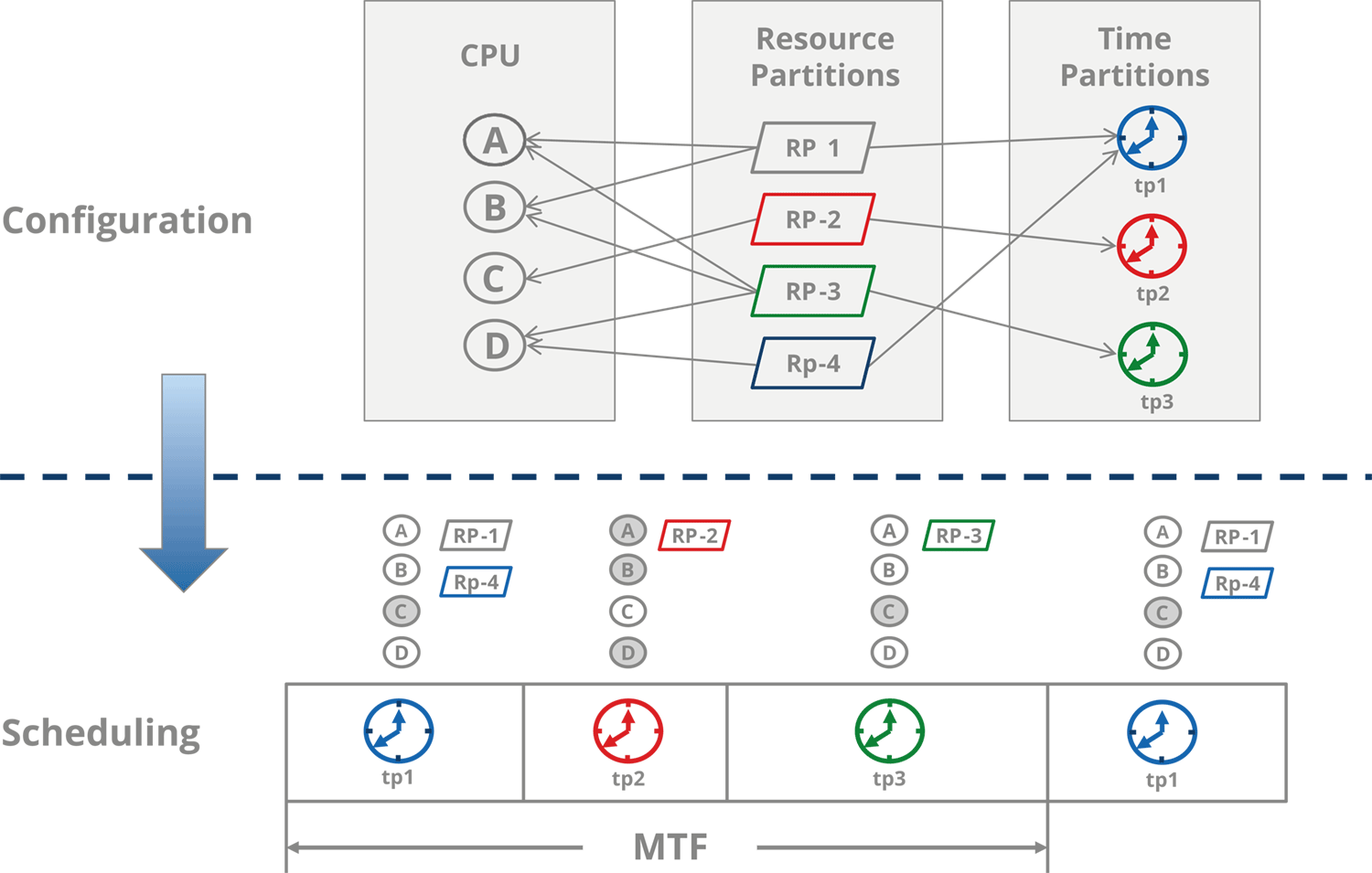
The scheduler executes a common Major Time Frame (MAF) which keeps the OS fully ARINC 653 compliant. CPU cores are statically assigned to resource partitions where one resource partition may utilize multiple cores. Figure 5 shows a possible configuration of the PikeOS partition scheduler:


Figure 5: Example Configuration and Run-Time Model using the PikeOS Partition Scheduler

The assumed platform is based on a quad-core CPU. The major time frame is divided into three partition windows.

One critical single core application shall have exclusive access to one of the cores and have exclusive access to the entire platform during its time window. One performance-demanding partition shall have exclusive access to the remaining three cores during its time window. One time slot is shared between two resource partitions. One partition running on two cores and another running on one core.o n During on time window entire platform during its time window.

The selected configuration focus on a maximum level of isolation for the critical application accepting a significant waste of CPU time. Partition 3 is the only partition executing on core 'C' and during the time slice of time partition 3 there is no other partition execution. This eliminates any interference on hardware and software level. The level of determinism in this configuration is even better than on a traditional IMA platform since the critical application does not share the core with other partitions which also keeps the state of the private caches unchanged. This is of course a quite expensive configuration since 5 of 12 time windows in a Major Time Frame are unused.

A configuration which is comparable to existing IMA configurations would allow to use core 'C' during Tp_1 and Tp_2 would reduce the amount of unused time windows to 3.


Conclusion

The use of multi-core CPUs is necessary for future avionics platforms including IMA platforms in order to deal with the increasing performance requirements. A major concern is the complexity of these CPUs, especially if they are provided as MPSoCs. Multi-core CPUs need to be introduced into avionics in less critical systems to gather in service experience and evaluate if they are usable for critical systems. To get enough data a cooperationwithin avionics industry may be required. Multi-core platforms may introduce additional hardware and software interference channels between partitions executing concurrently on different cores which need to be eliminated by a smart system software design. The processor selection should take the effects of shared caches into account and the platform design must avoid any shared interrupts and pay attention to I/O buses and I/O devices.

We used the operating system PikeOS to demonstrated that an ARINC 653 compliant OS can support multi-core CPUs in an IMA compliant way. A platform can be configured in a way that critical applications behave even more deterministic than on today's IMA platforms if a certain amount of unused bandwidth is acceptable. Due to the increased performance, multi-core platforms can contribute to more safety since they can provide the necessary performance to implementation additional redundancy.


References

[1] Dr. Eugene Normand, December 16, 1998, Single Event Effects in Avionics, Boeing Radiation Effects Lab, (C-17-SEU-Present.pdf)

[2] Philip P. Shirvani and Edward J. May 2001, McCluskey, SEU Characterization of Digital Circuits Using Weighted Test Programs, Center for Reliable Computing, Stanford University

[3] Udo Steinberg, 29.04.2010, Parallel Architectures - Memory Consistency & Cache Coherency, Technische Universität Dresden, Department of Computer Science-Institute of Systems Architecture, Operating Systems Group, os.inf.tu-dresden.de/Studium/DOS/SS2010/02-Coherency.pdf

[4] Tian Tian, Chiu-Pi Shih, February 24, 2009,Software Techniques for Shared-Cache Multi-Core Systems, Intel Software Network, http://software.intel.com/en-us/articles/software-techniques-for-shared-cache-multi-core-systems/

[5] OpenMP Architecture Review Board, May 2005, OpenMP Program Interface, Version 2.5, OpenMP Architecture Review Board

PikeOS RTOS & Hypervisor

PikeOS
RTOS & Hypervisor

Learn more

PikeOS for MPU

PikeOS for MPU

Learn more

ELinOS Embedded Linux

ELinOS
Embedded Linux

Learn more

Need more Information?


Contact us