Professional Articles

Railway & Transportation

A Modular Train Control System through the Use of certified COTS HW/SW and qualified Tools

The European Rail Traffic Management System (ERTMS) forms the basis for standardization in relation to train control systems (ETCS), command control and safety technology, and Integrated Electronic Control Centres (IECC) in Europe [ETC16]. The previous HW/SW systems in these fields followed a monolithic integration approach applied by the individual manufacturers. This harbours problems relating to the compatibility of the systems of the various manufacturers, creates dependencies and reduces the diversity of solutions, by means of which safety-critical HW and SW defects find appropriate potential for their dissemination [HAS16, HAS08].

In addition, for market access companies have had to deliver complete solutions. New developments are aimed at the modularization of the functional architecture and at digitization in the infrastructural area, which enables construction of these HW/SW systems from Commercial Off-The-Shelf (COTS) components from various manufacturers. In addition, the intention is to achieve flexibilization of the systems, cost reduction through an increase in the variety of suppliers for COTS components and a shortening of the development cycles. The challenge is to be able to implement the modularization within the processes for the system development, system integration and system certification in order to realize the benefits aimed for. In addition, the suppliers of COTS components then also gain access to the rail control market, for which a growth of between €13bn and €14bn is forecast for the years 2017 to 2019 [WRM14].

This paper evaluates this modularization and the challenges of the latter within the implementation of a demonstrator, which serves as a proof of concept study and is being continuously developed further. The following framework conditions are set for possible problem-solving approaches in relation to the implementation of this study:

  • The aim is to employ model-based approaches and use the existing COTS components for the software development process. This allows formal verification at an early stage in relation to the satisfiability of system requirements, by being able to perform incremental model-based simulations of the overall system.
  • For the certification process the use of semi-formal methods are to be evaluated that correlate the existing certification in comparison to standards by way of the COTS components with the requirements in the specification of the overall system and that reduce the necessary certification of the overall system to the difference ascertained [MIL16].
  • The safety-related standards EN-5012x are to be evaluated and taken into consideration in the study in accordance with the domain [EN126, EN128, EN129, EN159]. 


Figure 1: Diagrammatic Structure of the Railway Demonstrator

The planned basic structure of the demonstrator comprises three modules, each of which is composed of different components. The diagrammatic structure can be seen in Fig. 1, being as follows:

  • The rail module comprises the complete physical construction of a model railway complete with vehicles, railway network and location information references (balises). The model trains themselves are equipped with adapted hardware and software that communicates with the train protection system. Both the railway network and the vehicles are connected via an IP-based network to the other modules. The plan is to replace the model railway at a later point in time with a simulation model so that more complex scenarios can be covered.
  • The safe-PC module separately combines the guideway calculation as an abstract Integrated Electronic Control Centre (IECC) and the ETCS kernel component 'Speed and Distance Monitoring' (SDM) of the individual vehicles.
  • The panel-PC module is for the purpose of ETCS-compatible visualization of the train protection information as envisaged for the driver's cab.
  • Available multicore systems are envisaged for the railway control market as hardware (HW) platforms for safe- and panel-PCs. 

The following sections describe the present status and knowledge gained from the implementation of the demonstrator. Section 2 shows the integration concept and the individual components complete with their development steps. Section 3 records the present status of implementation. Section 4 deals with the certifiability of the individual components and section 5 concludes the paper with a summary and the outlook for the next iterations.


Concept of the Train Control System

The planned concept for the train control system of the demonstrator envisages the use of COTS and a reduced own share of the development work for the components. The starting basis for integration of the modules from Fig. 1 is as follows: 

  • The HW platforms for safe- and panel-PCs are the tried and tested COTS components VX3035 and TRACe HMID104 from the company KONTRON, which were designed for the railway market and have at their disposal multicore processors.
  • The PikeOS Hypervisor from SYSGO, being the COTS component complete with available expansions, is used as the operating system for the safe-PC and panel-PC modules. On both PC modules the first expansion relates to the Certifiable IP Stack (CIP) in order to guarantee the IP-based network communication (ETH/IP). In addition, the CoreAVI component for OpenGL-based representation of the ETCS Human-Machine Interface (HMI) is used on the panel-PC module.
  • In order that the ETCS components required for a demonstration are able to be implemented, platform-independent SCADE models from the openETCS project [ETC16] have been resorted to for the HMI and kernel component SDM. This step of integrating components via the SCADE suite thus complies with the model-based approach. The SCADE suite provides the direct generation of source code from the SCADE model for PikeOS.
  • For integration of the functional SW components on the PikeOS separation kernel for the safe-PC and panel-PC, initial resource and time partitioning are performed by corresponding integration projects in accordance with the necessary safety requirements so that the functional components are able to operate free of interference.

The rail module provides the complete physical simulation of several vehicles on the balise-equipped model railway network. Both the vehicles and the railway network are connected via the IP-based network to the safe-PC. The vehicles communicate their current positions to and receive the resulting releases or braking interventions from the train protection system on the safe-PC. 


Figure 2: PikeOS Time Partitioning for Component Partitions on the Safe-PC Module

On the safe-PC module there is for each vehicle in the rail module an SDM component that evaluates in interaction with the IECC component the braking curves and generates critical braking interventions. The IECC component processes the received track data of the rail module. This enables interactive selection of the guideway through the switching of the points relative to the runtime. In this way dynamic conditions for speed limitation or collision avoidance can be created. Both the IECC and the openETCS components are generated directly from the corresponding SCADE models. 

A network adapter is available on the safe-PC module. The incoming and outgoing network packages are thus distributed to the model components via a corresponding partition (NETMUX) in accordance with the multiplex method. This NETMUX component is the only own development with a minor degree of complexity. Separation is performed via network ports and the trusted Shared Memory (SM) mechanisms of PikeOS are used for the internal communication.


Figure 3: PikeOS Time Partitioning for Component Partitions on the Panel-PC Module

In addition to the vehicles of the rail module the safe-PC communicates the current data to the respective openETCS-HMI on a panel-PC. This is generated as OpenGL-compatible software directly from the corresponding SCADE display model of the openETCS library. An additional CoreAVI driver component from Core Avionics & Industrial Inc. is used for the OpenGL-compatible connection. The output therefore takes place by means of the panel-PC module, as exists in the driver's cab of a rail vehicle. 

In addition to the resource partitioning of the individual components of the respective modules in Fig. 1, a chronological partitioning for these components, as shown in Fig. 2 and Fig. 3, also takes place.


Implementation Status of the Demonstrator

Within the context of the diagrammatic structure of the demonstrator, as shown in Fig. 1, the rail module and the safe-PC module were able to be implemented in the form of one prototype in the latest iterations. Implementation of the panel-PC module is envisaged for the next iteration. This prototype was exhibited by SYSGO GmbH and the correct functionality of the networked ETCS components demonstrated at Embedded World 2016. A VX3035 (3HE VPX SBC with Intel Core i7 processor) was provided by KONTRON for the HW platform A.

The demonstrator claims to realistically simulate the aspects represented. The formal model components of the openETCS kernel are integrated without change. For the purpose of adaptation to the demonstrator the components are surrounded by adapted translation modules. The details on the implementation and interaction of the ETCS components are as follows:  

  • The model railway vehicle combines true-to-scale drive control, odometry and balise readers. The drive control is located on the respective vehicles of the rail module and simulates the running behaviour independently of the train protection system on a scale of 1:160, including evaluation of the location balises within the line section for synchronization of the odometry. These balises operate by means of infrared transmission (IrDA). Integration of the vehicle control within the model railways was performed by means of a hardware expansion on the basis of an Atmel XMega32E5 microcontroller (MCU). Complete integration of the complex ETCS component for braking curve monitoring in consideration of gradients, non-linear braking behaviour and successive braking points on the model vehicle is currently not possible and is not envisaged for the demonstrator. The concept therefore envisages the concept of the application-compliant safe-PC module. The realizability of such concepts can be partially evaluated through this step of separated integration on internetworked systems.
  • The guideway calculation (IECC), implemented in the form of a formal SCADE model on the safe-PC module, is a special component. The dynamic line plan of the model is read in from the point controller of the rail module via the network and the necessary and maximum guideway is calculated for each vehicle. Various ETCS components on the line face and vehicle face are merged for this purpose. The guideway calculation within the IECC component therefore also fulfils the ETCS kernel function of the position report and track atlas.
  • Furthermore, the integration of ETCS mode in favour of a simplified demonstration was waived. After connection setup between the devices the vehicle switches over straightaway to Full Supervision mode (FS). As the position on the model railway board is not known to the vehicle until a location balise is overrun, a virtual On-Site mode (OS) is generated in the FS, in which the guideway is limited to 1000 m at a speed of 50 km/h.

Through the secured separation by means of PikeOS, both the SDM components of all three model vehicles and the central IECC component can be separately integrated free of interference on one platform. In summary, the implementation of rail-PC and safe-PC modules has succeeded in connecting the selected components of the openETCS kernel with the physical demonstration. 


Certifiability of the Train Control System

The requirements for the functional safety of rail system equipment are described as follows in the national and European regulations, last but not least in the CENELEC series of standards EN 501XX: 

  • EN 50126 deals with the aspects of reliability, availability, maintainability and safety (RAMS) of the complete infrastructure and also of the individual subsystems.
  • EN 50128 describes the process and the technical requirements for the development of software for programmable electronic systems [EN128].
  • EN 50129 must be applied for safety-related electronic systems used in signal engineering [EN129].
  • EN 50159 must be applied for safety-related communication used in transmission systems [EN159]. 


Figure 4: Diagrammatic Overview for the Purpose of Implementation, Verification and Validation

Upon completion of the prototype phase a strategic concept for simplified certifiability in consideration of these standards and of the existing certification, testing and model artefacts of the COTS components is to be evaluated. The tangible objective is to be able to reduce the resulting costs and the expenditure for a certifiable overall system. In the process the methodology will be aligned with the approaches of the EURO-MILS project [MIL16], which is concentrated on the security sphere. The safety requirements of the overall system will be compared with the existing certification artefacts of the COTS components for the demonstrator. In a semi-formal review process the outstanding requirements will be identified and the safety requirements delta ascertained will then represent the minimized starting basis for certification of the overall system. This way the expenditure on the integrator of the overall system should be reduced to the procedure as shown in the upper part of Fig. 4 in accordance with the verification and validation model.


PikeOS Hypervisor Component

The underlying operating system, represented by the PikeOS Hypervisor component, assumes a central role for the realization of security functions in software in accordance with EN 50128. 


Figure 5: PikeOS Software Architecture

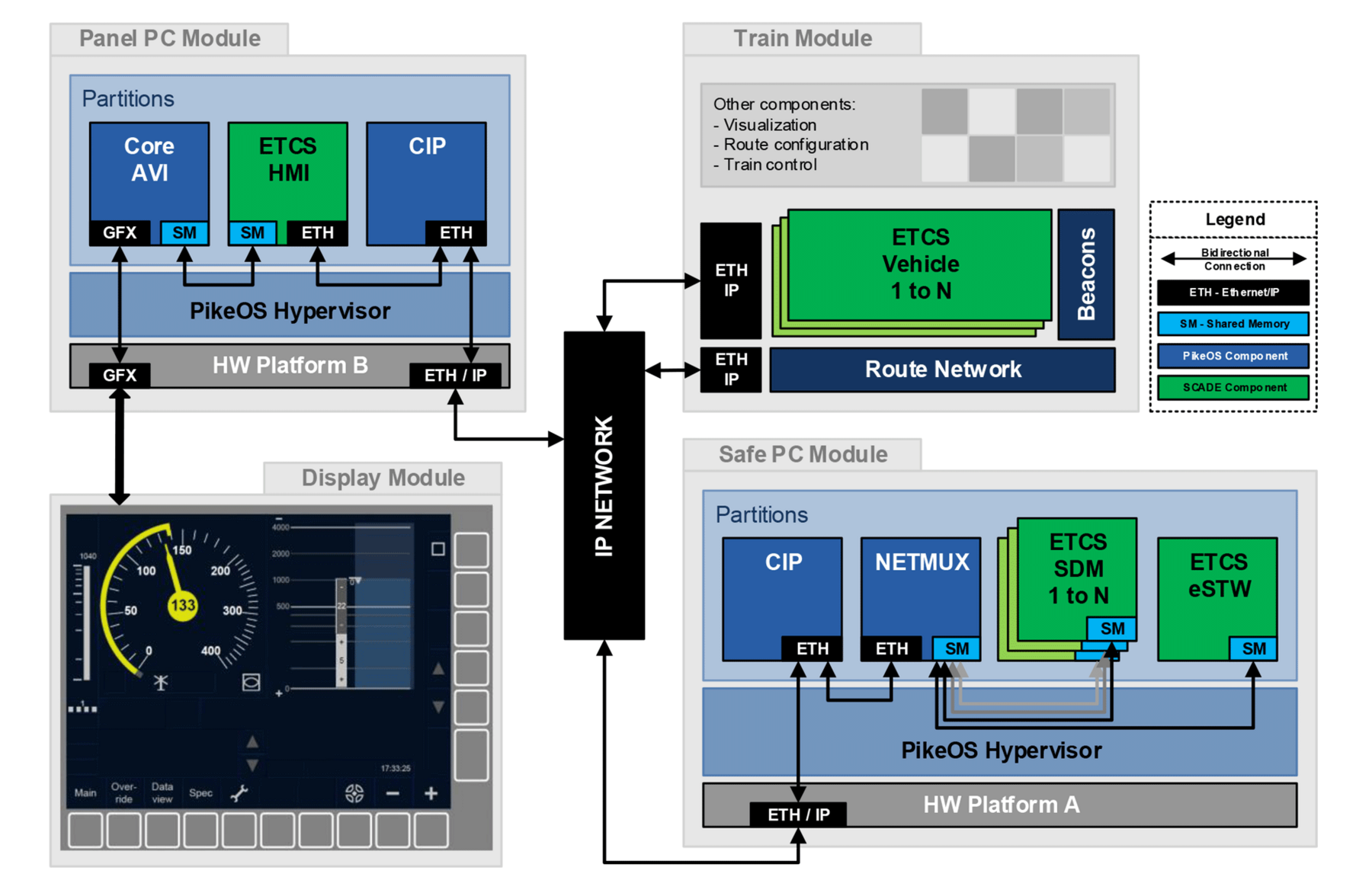
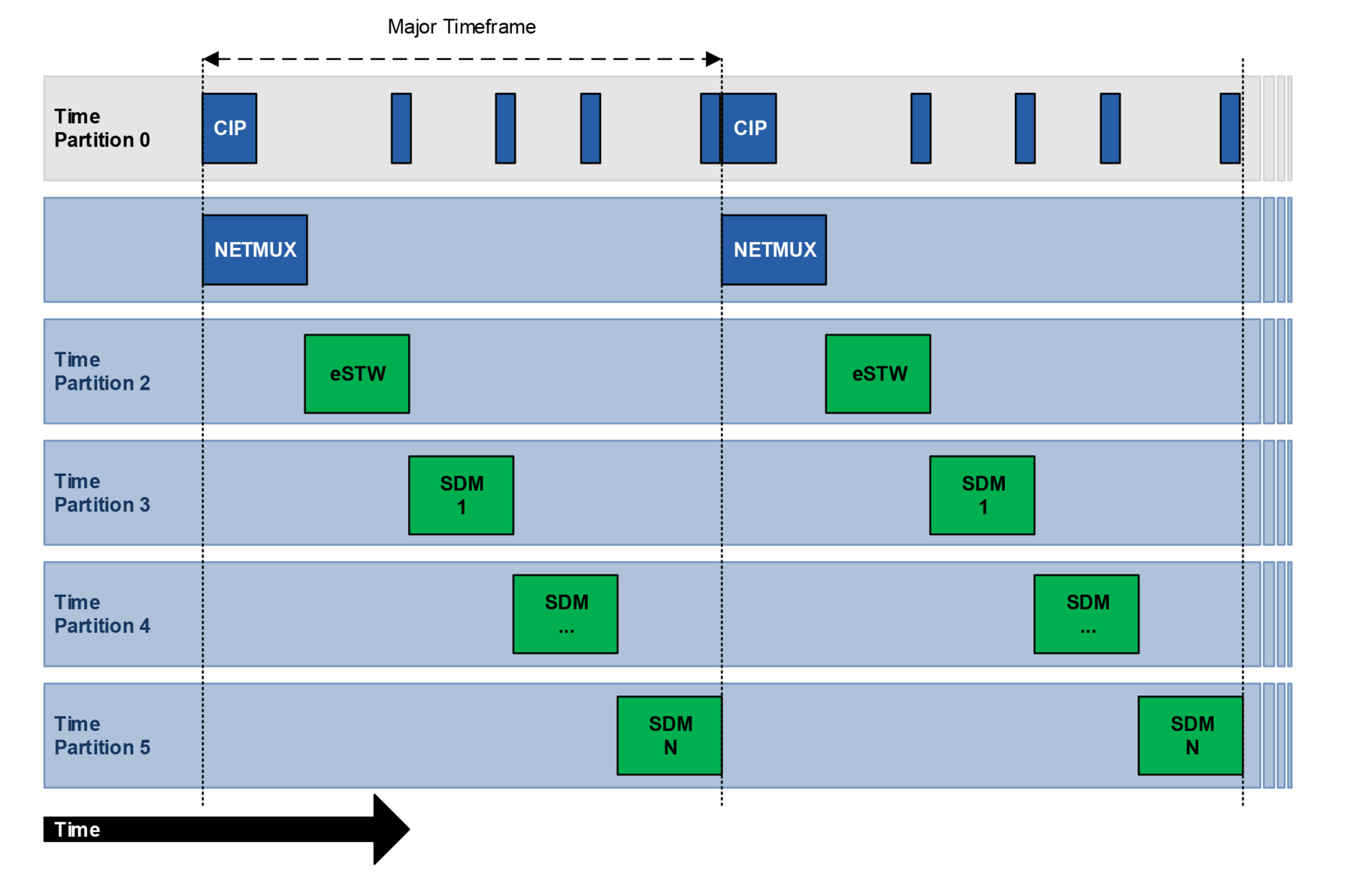
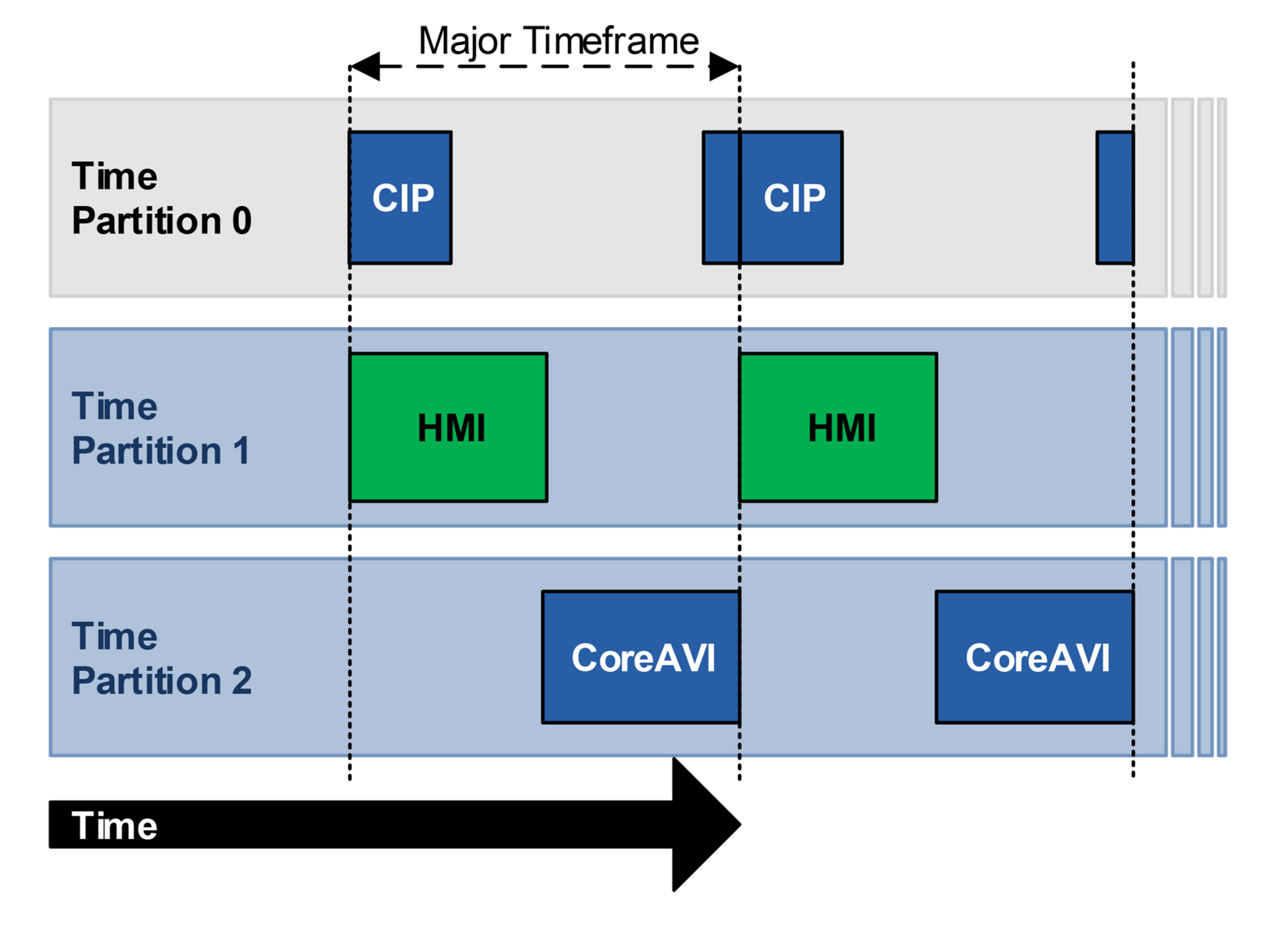
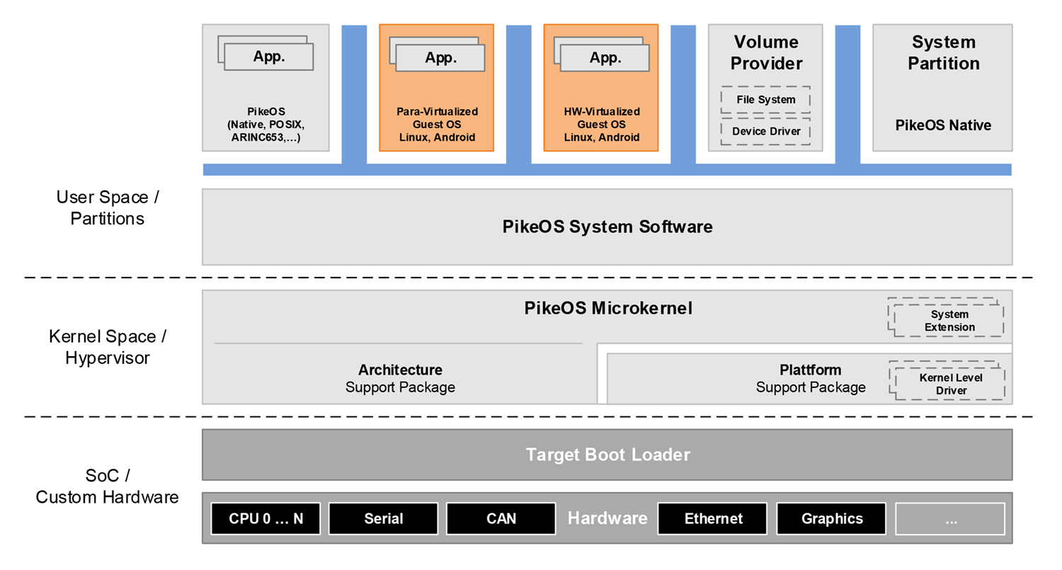
The basic principle of this separation kernel is that the partitioning of the hardware platform is manipulation-proof and static [WIK01]. Furthermore, its Trusted Code Base (TCB) is small enough for it to be verifiable at an acceptable cost. SYSGO's PikeOS is a special implementation of a separation kernel and provides partitioning on the basis of a microkernel, as illustrated in Fig. 5. PikeOS thus unites a real-time operating system and Hypervisor in one product. On the one hand the partitions can run operating systems like Linux or Android, while on the other hand providing a container for runtime systems such as POSIX®, AUTOSAR, ARINC 653. In addition, PikeOS allows via the chronological partitioning the assurance of a Worst-Case Execution Time (WCET) in accordance with EN 50128 [MOE01]. A suitable concept on the basis of the separation kernel can drastically simplify certification. In the rail industry both train control systems and software-based control centre systems are already using the separation concept to ensure software-based SIL4 security on their respective hardware platforms. In this case a separation kernel guarantees reaction-free separation so that applications with mixed criticality levels can be consolidated on one hardware platform. Safety functions, communication services and convenience functions can thus be provided simultaneously on hardware, as a result of which the size, weight and power consumption (SWAP) are optimized.

The development process for PikeOS fully meets the requirements of EN 50128, i.e. complete process documents and artefacts are available. In accordance with Section 7 of EN 50128:2011 an operating system can be considered as being generic software on the basis of which a number of installations can be created by simply providing application-specific data and algorithms. Generic software can be certified as an individual component independently of the system. PikeOS already has certifications in accordance with SIL4 for various processor architectures and multicore systems. At the same time PikeOS already meets the necessary requirements for the process of incremental certification, as is envisaged for modular systems in the field of avionics, so that existing certification artefacts can be reused subject to fixed conditions, if the existing system is modified or expanded by other modules.


Hardware Platform Component

The dangers that emanate from the hardware consist of failure of the corresponding components and the malfunctioning associated with this. A top-down method, such as fault tree analysis, or alternatively a bottom-up process, such as a Failure Mode and Effect Analysis (FMEA), is recommended for the purpose of analysing the dangerous failure types [EN129], identification of the failure types to be expected of all hardware components being demanded. For integrated circuits with System-on-Chip (SoC) the failure types are difficult to determine in advance on account of the complexity or due to the programming of the hardware they are very dependent on the respective application. In appendix C3 the standard proposes that a justification be supplied that this failure type cannot occur plausibly on account of the software architecture. If this is not possible, the failure type can be alternatively detected externally and a safe status can be adopted within a required time. On account of the complexity of the Intel Core i7 based VX3035 hardware used in this case, the safety concept for the SIL 4 certification takes into consideration external detection of the hardware failure. The monitoring of the defect-free functioning of the hardware can be ensured by various Built-In Tests (BIT), which can be subdivided into the following categories:

  • Power-On BIT (PBIT): these tests are executed either by the firmware or during the boot phase of the operating system. As certification of the BIOS code is too expensive, a predefined register configuration is tested as a PBIT, which must be achieved by a correctly operating BIOS. If, after booting, the register configuration differs from the specifications (due to defective or non-available hardware), the system does not go into operation.  
  • Continuous BIT (CBIT): tests that are executed at runtime are dependent on the peripherals used and on the application. As the correct functioning of this test is safety related, the CBIT code is subject to SIL 4 certification.  RAM errors are detected by the use of ECC RAM.

The safe status that must be adopted in the event of an error is likewise application dependent and is not to be considered further at this point. For the sake of completeness it must be mentioned that redundant architecture, such as Triple Modular Redundancy (TMR), is necessary for the SIL 4 system safety concept.  


Project-specific Software Components

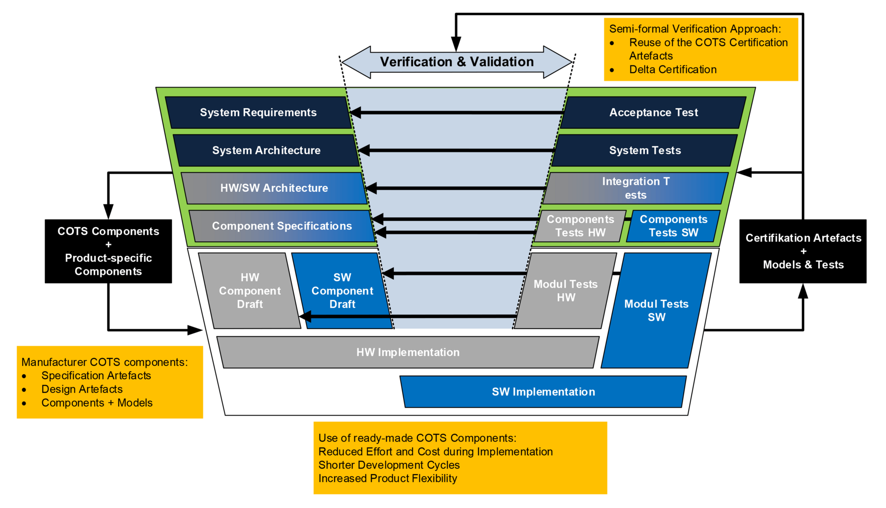
The life-cycle of systems developed in accordance with EN5012x envisages different phases that are described by the verification and validation cycle shown in Fig. 4. In the openETCS project, formal methods were invoked for the systems analysis, architecture modelling, functional modelling and behaviour modelling [OE16].

The System Requirements Specification (SRS) is available for ETCS and can therefore be used directly as an input document for the ETCS-specific components. The document must be converted to a corresponding format (ReqIF) in order to be able to create the required traceability. In the project openETCS the tool Subset-2-ReqIF, which classifies structured documents into formal requirement files, has been developed for this purpose.  These are used for import into corresponding tools such as ProR/ReqIF, ReqCycle and Ansys SCADE LifeCycle. From the SRS the system structure is initially developed (e.g. Papyrus, Ansys SCADE system) to then successively model the individual components on the basis of the specification (Ansys SCADE Suite). In order to be able to already generate and automate tests at an early stage, tools such as SCADE Test are available, which can already run tests that are integrated on the development-PC platform [HAS16].

If a SCADE model has been verified by means of the model check, formal verification and timing&stack verifier, a verified C-code is generated by the qualified code generator (KCG). This code is an ANSI C-code without any dependencies on hardware or special libraries. To connect the inputs and outputs of the model with the sources and sinks of specific hardware and to give the model a specific timing, corresponding abstraction code must now be created. The scope of this platform code should be minimal, because it has to be verified and can only be reused under certain conditions. The combination of a generated C-code and platform code must be translated into a target binary at the end. At this point it is evident that the use of a certified operating system offers considerable advantages. Even if the underlying hardware is changed, the platform code between the PikeOS-API and the SCADE model can be retained. The main cost for the integration of full-value, certifiable ETCS components within the demonstrator is reduced to the selection of corresponding tools. The existing models can be used for early-stage tests. 

Documents and artefacts in accordance with EN 50128 that can be invoked for certification of the (sub)system also exist for the software components Certifiable IP Stack and CoreAVI OpenGL ES.


Summary and Outlook

Upon completion of the first iteration relating to implementation of the train control demonstrator on the basis of existing COTS components it is clear that the assumptions made in relation to reduced costs for system integration and for possible certification are justified. About 4 man months were invested to achieve the present status of the demonstrator and it was subsequently possible to connect via the network the ETCS components on the safe-PC module fully with the physical simulation of the rail module. The next integration step will complete and thus finalize the prototype and the panel-PC module. Elaboration and evaluation of the certification method presented will then take place.


Authors

Dr.Eng. Frank Golatowski and Thorsten Schulz M.Sc.Eng.
frank.golatowski@uni-rostock.de
thorsten.schulz@uni-rostock.de
Institute for Applied Microelectronics and Data Technology
Rostock University

Mehmet Oezer M.Sc.Eng. and Philipp Gorski M.Sc.Eng.
philipp.gorski@sysgo.com
SYSGO GmbH
 

References

[WRM14] Roland Berger Strategy Consultants, World Rail Market Study forecast 2014 to 2019, 2014, Commissioned by UNIFE The European Rail Industry, ISBN: 978-3-7771-0468-3

[MIL16] EURO-MILS, 2016, Publications & Deliverables, [ONLINE] Available at: https://euromils-project.technikon.com/, [Accessed 28 June 2016]

[EN126] DIN EN 50126:2000-03, Railway applications - The specification and demonstration of reliability, availability, maintainability and safety (RAMS)

[EN128] DIN EN 50128:2012-03, Railway applications - Communications, signalling and processing systems software for railway control and monitoring systems)

[EN129] DIN EN 50129:2003-12, Railway applications - Communications, signalling and processing systems - Safety related electronic systems for signalling

[EN159] DIN EN 50159:2011-04, Railway applications - Communications, signalling and processing systems - Safety related communication in transmission systems)

[ETC16] openETCS Consortium. 2016. openETCS. [ONLINE] Available at: openetcs.org. [Accessed 29 June 2016]

[HAS08] Hase, Klaus-Rüdiger; openETCS: Speed Up Migration & Reduce Total Cost; www.uic.org/cdrom/2009/01_ERTMS-platform/docs/5-steering-meetings/05-18nov08/Proceedings/item5-openETCS-hase.pdf

[HAS16] Hase, Klaus-Rüdiger; openETCS: Model-based, Agile and Open Source; www.schienenfahrzeugtagung.at/download/PDF2016/MiV07_Hase.pdf

[OE16] Mahlmann, Peter et. al; openETCS: Development and Implementation of the 'Open Proof' Concept [..] (concluding report); github.com/openETCS/Dissemination/blob/master/Schlussbericht/openETCS_Schlussbericht.pdf

[MOE01] Özer, Mehmet; White Paper: PikeOS Safe Real-Time Scheduling; https://www.sysgo.com/whitepapers

[WIK01], Wikipedia: Multiple Independent Levels of Security en.wikipedia.org/wiki/Multiple_Independent_Levels_of_Security

PikeOS RTOS & Hypervisor

PikeOS
RTOS & Hypervisor

Learn more

PikeOS for MPU

PikeOS for MPU

Learn more

ELinOS Embedded Linux

ELinOS
Embedded Linux

Learn more

Need more Information?


Contact us